Operational Overview
The diagram below shows the specific parts of the sensor. Read further to explore the functionality of each part of the sensor.
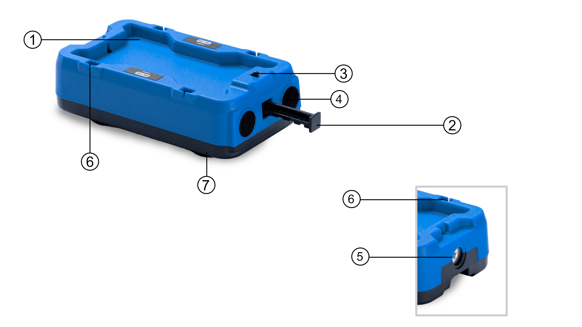
Bay for masses (1)
The 2 x 280 g masses, supplied with each cart, can be stacked here.
3-Position Plunger (2)
The spring-loaded plunger has three positions for firing/releasing the plunger.
Plunger release button (3)
This button is used to fire/release the plunger.
VelcroTM Buffer (4)
Each cart has VelcroTM fitted, for easy connection.
Connection for spoked pulley string & magnets (5)
This is where the magnets are connected, and string can be attached to use the spoked pulley. Please see worksheets, which can be found on our website, for more information.
Interrupt card slots (6)
When using Light Gates, this is where the double/single interrupt card is fitted.
Wheels (7)
The spring-loaded wheels - adapted to give optimal performance under different loads.