Operational Overview
The diagram below shows the specific parts of the sensor. Read further to explore the functionality of each part of the sensor.
The conductivity electrode
The conductivity electrode has two carbon plates of known size facing each other across a cell of a known width. The relationship between the electrode size and the separation is used to create the K value. For the supplied electrode, the K value = 1. If you used a different electrode with a different K value, the output values would not be correct.
1 = The temperature sensor used for temperature compensation.
2 = The cell
3 = The carbon electrodes
Measurement procedure
- If possible, soak the tip of the Conductivity electrode in deionised water for about 30 minutes to make sure the electrodes are clean. If not, rinse the tip thoroughly with deionised water before use.
- Wipe the outer part of the electrode body with a clean paper towel. Shake vigorously to remove any droplets from the cell chamber. If possible, wash the tip in a sample of the solution to be tested.
- Place the Conductivity electrode in the sample to be tested. The sample must be at least 3 cm deep to ensure the cell chamber is fully submerged.
- Stir the solution gently to get rid of any air bubbles that could be trapped in the cell chamber. Wait for 10 seconds to allow the readings to stabilize.
Note: If you are taking readings in a solution that has a temperature below 10ºC or above 35ºC, allow more time for the readings to stabilize.
- If the value is above, below, or near to the maximum or minimum value in the current range, alter the selected range of the Sensor.
- Clean thoroughly when testing is complete to avoid any contamination when the electrode is next used.
User calibration
The sensor is calibrated to the design specification, which assumes a known separation of the carbon plates, a known area for the plates, and a known current across the cell. It is understood that manufacture and tolerances can change one or more of the expected parameters.
If the sensor gives a result that is far out (the conductivity readings are most accurate over the middle section of each range), it can be calibrated.
You will need two solutions of known conductivity (purchased or made to one of the many recipes available on the internet).
In devices, click on the calibrate button and place the electrode into the lower known solution, follow the on-screen directions. The calibration only applies to the range selected. It is best to use a known that is midway to the range being calibrated, for example use knowns of 50 -80 us on the 0 – 100us range.
Once you have selected OK the calibration will be stored as a user range. The calibration only holds for the electrode / sensor combination. If the sensors are separated from the electrodes, they will need re-calibrating.
As the electrode ages it will need calibrating more frequently due to contamination build up. To reduce the contamination build up clean the electrode in deionised water after each use.
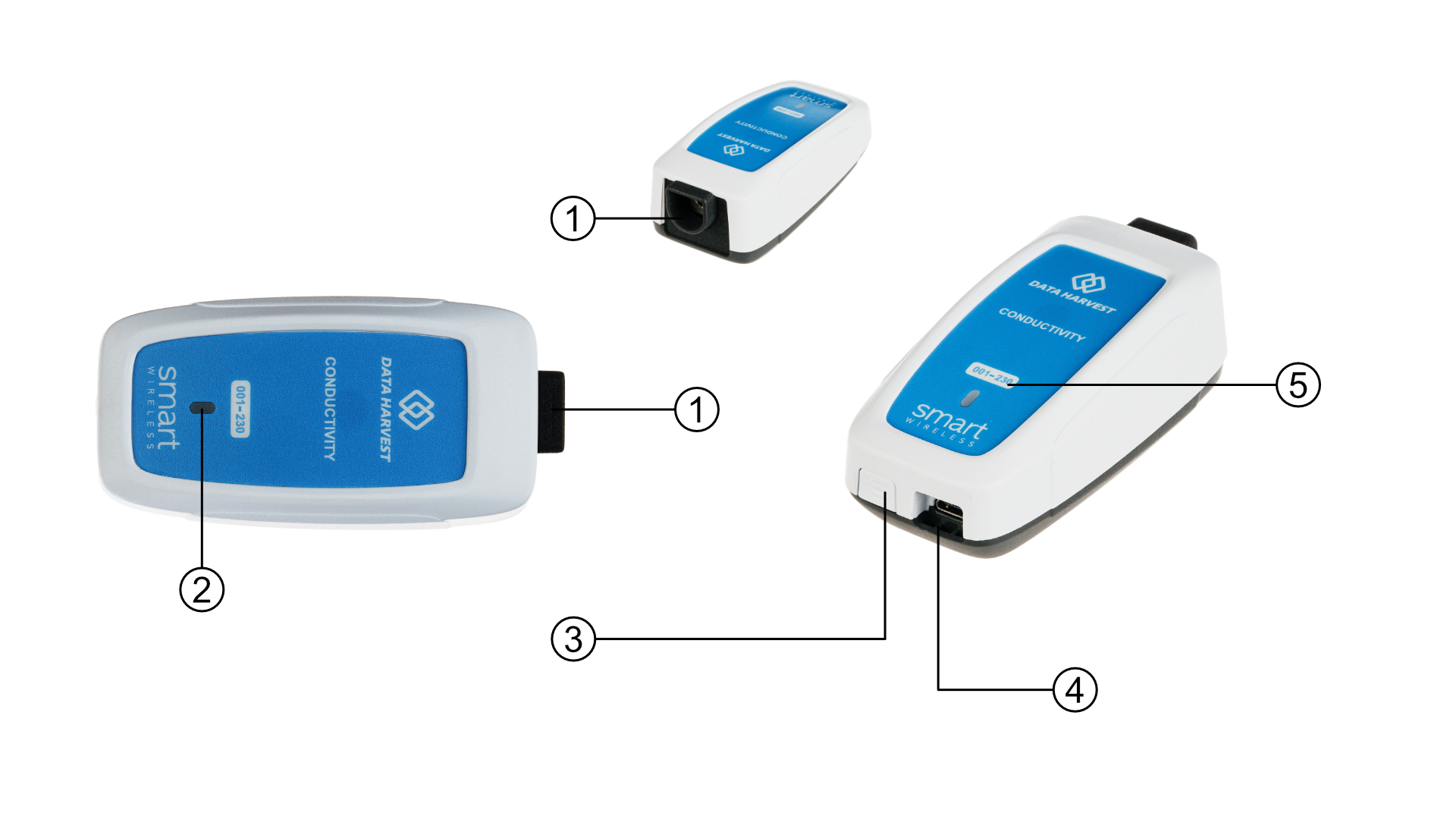
- Sensor End Cap
- Status Indicator
- On/Off Switch
- USB Port
- Unique ID Number
Sensor End Cap (1)
Most Smart Wireless Sensors feature an end cap that is specific to the requirements of the device's internal sensor. The sensor's end cap is the direct interface between the device’s internal sensor and your experiment.
The Status Indicators (2)
The sensor features a single status indicator that changes colour and flashes. See the table below for further information.
|
Status Light |
Indicates |
|
|
No light |
|
Sensor is Off. Short press the On/Off switch |
|
Blue flashing |
|
Sensor is On and Bluetooth advertising |
|
White flashing |
|
Charging via USB mains charger or USB port, Sensor is On and Bluetooth advertising |
|
Red, Green, Blue Flashing |
|
Charging via USB mains charger or USB port, Sensor is Off |
|
Green flashing |
|
Communication with the EasySense app (via USB or Bluetooth) has been established |
|
Solid Green |
|
Fully charged |
|
Orange flashing |
|
Recording data, a fast pulse indicates awaiting trigger in Remote Mode |
|
Red flashing |
|
Battery is low |
On/Off Switch (3)
The sensor's on/off switch allows you to turn the sensor on, off or perform a hard reset.
To switch the sensor off
- Press and hold down the On/Off switch until the white light shows, then release.
- If not communicating with the EasySense app, the sensor will turn off after a period of one hour of inactivity.
Hard resetting the sensor
- If necessary, attach the sensor to power.
- Press and hold down the On/Off button for at least 8 seconds until the status LED gives a flash of blue light, then release.
- If the sensor fails to respond, contact Product Support at Data Harvest. Please provide details of:
- The computer platform it is being used with and the EasySense app’s version number.
- A description of the problem being encountered.
USB Port (4)
Use to connect to a computer or a charging unit.
For specific USB or Bluetooth connectivity instructions, please see the 'Connectivity' section of this documentation.
For instructions on charging your device, see the section on 'Charging the Sensor'.
Unique ID Number (5)
All Smart Wireless Sensors are labelled with a unique ID number. This number is used in the EasySense app, so that you can identify each sensor when making a connection wirelessly.
The Sensor and EasySense
Please make sure that you use the latest release of the EasySense series of software. Both collection and analysis of data is available here, on a variety of operating systems.
Direct Data Logging
The sensor is designed to work directly with EasySense (as an installed application or PWA). A full compliment of experiments can be run by using the sensor through BluetoothTM or USB. EasySense will support direct logging and data storage when connected as above.
Remote Data Logging
The ability to capture data independently (free of a capture station) is done through EasySense’s Remote Mode.
This facility may be found in EasySense, under Setup. Once the conditions for data collection have been established, the sensor can be set to initiate collection for example, a rapid press of the power button. Initiation of the experimental data collection by the software is followed by remote detachment; collection is then on the sensor.
Data gathering is realised by using Setup once again.
Details are given in the latest EasySense User Guide.