Operational Overview
The diagram below shows the specific parts of the sensor. Read further to explore the functionality of each part of the sensor.
The Salinity Sensor has two component parts: the wireless sensor body and the electrode.
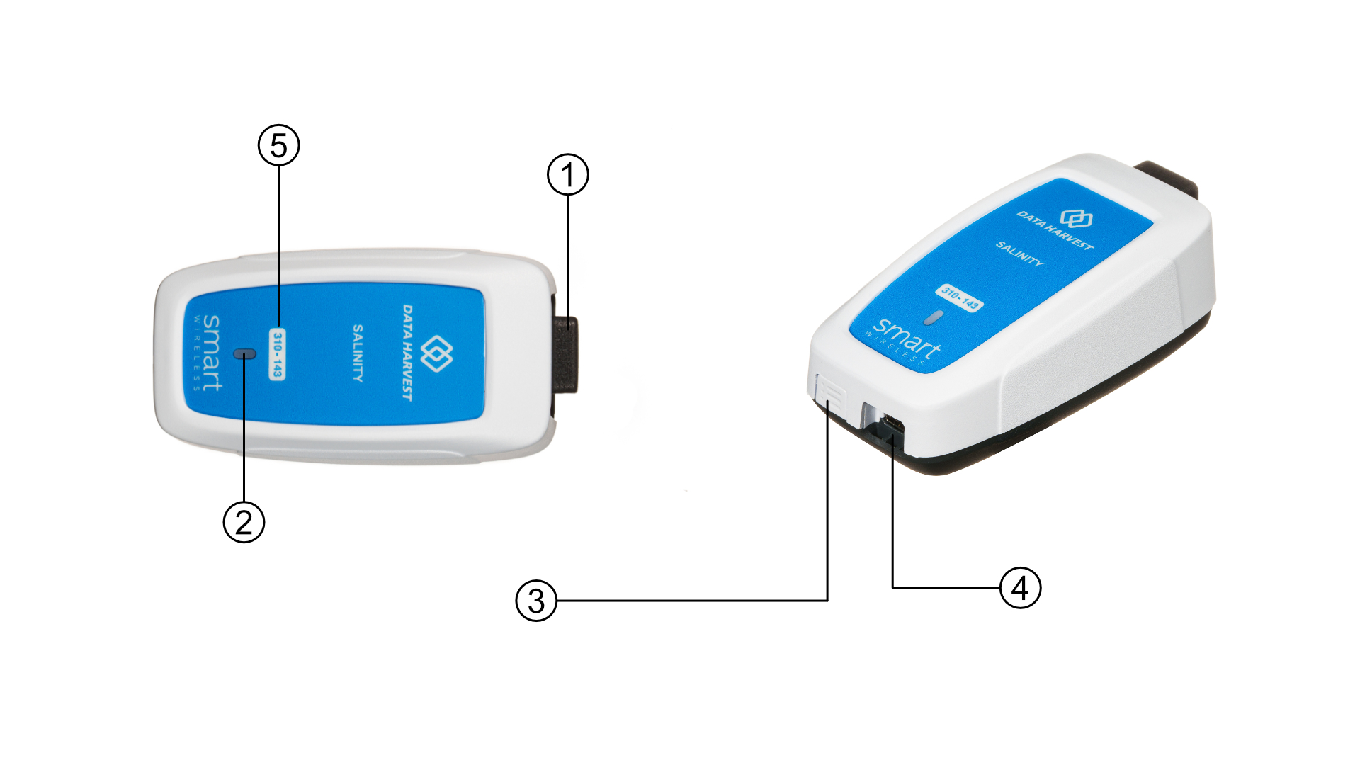
- Sensor End Cap
- Status Indicator
- On/Off Switch
- USB Port
- Unique ID Number
Sensor End Cap (1)
Most Smart Wireless Sensors feature an end cap that is specific to the requirements of the device's internal sensor. The sensor's end cap is the direct interface between the device’s internal sensor and your experiment.
The Status Indicators (2)
The sensor features a single status indicator that changes colour and flashes. See the table below for further information.
|
Status Light |
Indicates |
|
|
No light |
|
Sensor is Off. Short press the On/Off switch |
|
Blue flashing |
|
Sensor is On and Bluetooth advertising |
|
White flashing |
|
Charging via USB mains charger or USB port, Sensor is On and Bluetooth advertising |
|
Red, Green, Blue Flashing |
|
Charging via USB mains charger or USB port, Sensor is Off |
|
Green flashing |
|
Communication with the EasySense2 app (via USB or Bluetooth) has been established |
|
Solid Green |
|
Fully charged |
|
Orange flashing |
|
Recording data |
|
Red flashing |
|
Battery is low |
On/Off Switch (3)
The sensor's on/off switch allows you to turn the sensor on, off or perform a hard reset.
To switch the sensor off
- Press and hold down the On/Off switch until the white light shows, then release.
- If not communicating with the EasySense2 app, the sensor will turn off after a period of one hour of inactivity.
Hard resetting the sensor
- If necessary, attach the sensor to power.
- Press and hold down the On/Off button for at least 8 seconds until the status LED gives a flash of blue light, then release.
- If the sensor fails to respond, contact Product Support at Data Harvest. Please provide details of:
- The computer platform it is being used with and the EasySense2 app’s version number.
- A description of the problem being encountered.
USB Port (4)
Use to connect to a computer or a charging unit.
For specific USB or Bluetooth connectivity instructions, please see the 'Connectivity' section of this documentation.
For instructions on charging your device, see the section on 'Charging the Sensor'.
Unique ID Number (5)
All Smart Wireless Sensors are labelled with a unique ID number. This number is used in the EasySense2 app, so that you can identify each sensor when making a connection wirelessly.
The Electrode
The electrode consists of two platinum plates of known size separated by a gap of known distance. The ratio of the area of the plates and the distance of separation is expressed as a cell constant called the K value.
Mathematically this is described as K = L/a where L is the plate separation and a is the area of the plate(s).
The measure conductivity is the product of the measured conductivity x the cell constant. The unit of conductivity is the Siemen; this is a large unit and conductivity measured by this electrode will be in uSiemens. When the cell constant value is included in the measurement the unit should become uSiemens/cm.
An a.c. voltage is created on the electrodes and the current passing between the electrodes is measured. The current passes due to ions in the water being tested. More ions, more conductivity. The relationship between conductivity and current is essentially linear.