Usage Information
The Rotary Motion Sensor uses an optical encoder to describe the shaft position. This is a relative position indicator and will require the user to press the small zero button on the side of the sensor body to set the range to its mid-point (for example pendulum range) or its origin point (for example Distance ranges). Rotation ranges will not need to be zeroed. The encoder has a number of physical steps and an additional software tare will be required to set the exact zero.
Using the stepped pulley and ranges
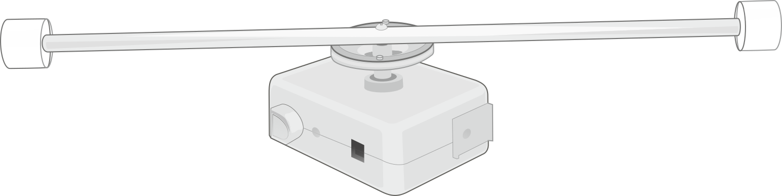
The front of the sensor has a three stepped pulley. The smallest pulley is closest to the body of the sensor and has a diameter of 11 mm. The mid-range pulley has a diameter of 31 mm. The largest pulley on the outer edge of the stepped pulley wheel is 49 mm. All diameters are measured from the base of the pulley groove.
To remove the pulley, unscrew the central retaining screw and pull evenly from the shaft. The shaft is keyed and will hold the pulley securely in place.
The central retaining screw is used for additional secure attachment of the pulley, and for attachment of the included pendulum rod.
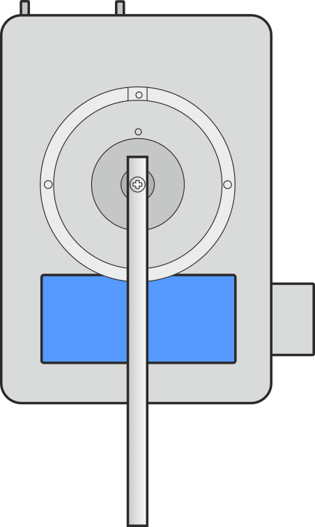
If you are using a thread to pass over the pulley and attach to something like a motion cart or spirometer, check the thread used fits into the base of the pulley and has sufficient friction to rotate the pulley.
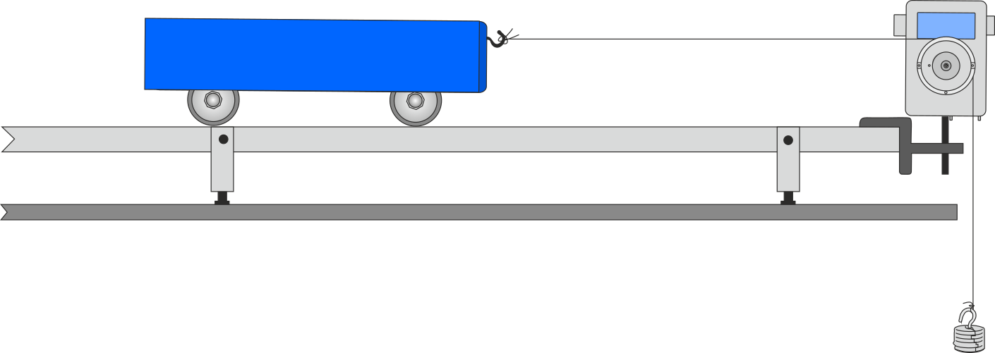
A small mass will need to be tied onto the thread to give tension to the thread and allow it to rotate the pulley.
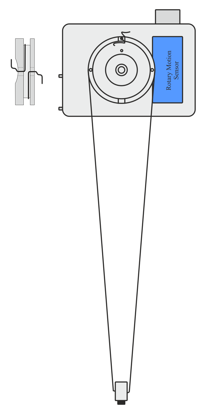
If you use a rod across the pulley groove you will have to calibrate for the distance. The pulley distance is for the diameter at the base of the pulley groove. Find the distance the rod moves for one complete rotation of the pulley (use markers to identify distance and rotation points) and then use the calculate tool to apply the correction factor to the data and give true distance. Use AX – BY with A being the multiplication constant and B = 0 to cancel out the BY function.
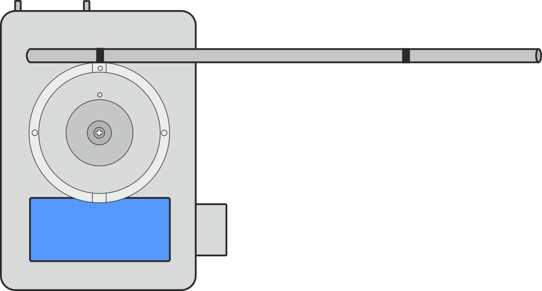
The distance between the dark lines on the rod is the distance of one rotation of the RMS pulley wheel
Using the pendulum ranges and rod
You can attach a pendulum in a variety of ways, for example:
- As a wire looped around the central securing screw
- Using the holes in the stepped pulley to attach a thread
Each has their own advantage. The pendulum rod is the simplest to use for quick studies as the masses that come with it allow you to quickly change the amplitude of the pendulum or the effective mass of the pendulum. The use of a wire or threads to create a pendulum can create very long pendulums but take longer to make changes.
Use an inter-sample period of 10 ms or greater for the best results.
The special pendulum range that is limited to 20 degrees of displacement should be used for pendulum work.
Angular Rotation Ranges
Studies of angular rotation will require the use of the optional accessory pack. Details of how to use the angular functions will be in the manual for that product.
Maintenance
If the sensor has not been used for a while it may require a few drops of light machine oil on the bearings to free them up.
If the sensor requires cleaning use a damp cloth for minor scuffs and marks. More persistent marks will require use of IMS or isopropyl alcohol.
Do not immerse the sensor body in any liquid.
Never use acetone (propanone) as it will dissolve the plastic case materials. Other organic cleaners should also be treated with great care. The plastic used for the case is ABS.