Usage Information
This Wireless Soil Moisture Sensor is designed to give accurate evaluations of soil moisture and to report these in a simple to understand format.
Water in the liquid state, has a high capacitance and consequently the dielectric constant of it compared to free space is about eighty times. So, when considering this property in soil, water has the dominant influence and water content can be measured. The sensor uses a capacitive measurement protocol; a single probe allows maximum measurement capability in terms of depth penetration and flexibility.
There are two commonly used metrics that are employed to evaluate the fundamentals of a soil's status, regarding crop health. The first is Volumetric Water Content, VWC, and its allied measurement Gravimetric Water Content, GWC. The second is a somewhat more subtle measurement known as the Soil Matrix Potential (see later notes). This second measurement is concerned with the availability of water based on the various forces within the soil matrix (soil suction). The latter and former measurements are related and can be mapped either using a calibration graph or, natively, a tensiometer.
Soil moisture characteristics depend upon the type of soil used. The capacity of soil to absorb water depends on the "free space" available for the water to occupy. In any calibration involving a particular soil type, one would ideally require soil with a state of almost zero water content and one with near saturation to generate a meaningful calibration. Field Capacity is the point at which all the pores have been filled with water and gravity- driven drainage has taken place: It is approximately 30 % in sandy soils and 50 % in clay. The general distribution seen in soil types is given in the diagram below.
The Soil Distribution Triangle

It is important to understand the basic composition of soil and how that is reflected in soil moisture readings. Appreciation of soil composition, its performance and how that is to be assessed should be considered before measurements are gathered. For example, a highly absorbent soil, such as clay may well accept a large volume of water, but it may not do so quickly. Sand, on the other hand, will not be so accommodating for water, but will absorb (and drain) in a shorter time. Experimental design may well be required to account for these variations.
Calibration Options
The sensor comes shipped with several calibration offerings. They are available in EasySense, Devices option.
Fixed Linear Calibration
The 70 % VWC standard will report the % VWC as a function of the dielectric response between air and water. This is a linear scale. The other fixed responses are detailed in Other Pre-Defined Calibrations (below).
Linear User-Defined Calibration
The 70 % VWC standard can be further modified by a two-point set of samples, to produce a linear response from those (see below). The following is a two-point calibration method that will report water values in a linear response format across the specified range.
1. Collect a representative sample of soil (more than 1 kg) for test.
2. Try to break up any large pieces and then filter through a 4 – 5 mm sieve.
3. Place the soil sample in a drying oven at 105˚C for 24 hours, if 0% will be referenced.
4. Transfer the dried soil to a sealable container using a measuring beaker once it has cooled. Try to
avoid water re-absorption during the process.
5. Record the volume of soil used and the mass for a first-time calibration.
Calculate the value of the density, ρ, from ρ = mass / volume.
6. Start the EasySense app, select Devices and connect the Soil Moisture Sensor.
7. Position the probe in the sample and make a note of the penetration depth (vertically, 10 cm).
8. Carefully pack the soil around the probe.
9. Make sure that there is sufficient coverage around the probe.
10. Carefully re-pack the soil again to give good contact.
11. Select calibration and calibrate this % VWC, point 1, using the known % VWC.
12. Remove the probe.
13. Add a controlled volume of distilled water to the dry soil. Make sure that the water is well integrated,
and homogeneously distributed into the sample.
14. Calculate the new Volumetric Water Content and optionally the Gravimetric Water Content
(% GWC for reference, optional see equation below).
15. Put the probe in the soil, taking care to ensure its placement, positioning, and ensuring soil contact
as above.
16. Calibrate for this sample % VWC (Point 2).
Non Linear User-Defined Calibration
If an alternative % VWC is needed for a complex soil mixture, a multi-point calibration should be produced. Using known % VWC values (x) and the output data from EasySense (y) in 70 % VWC range (without calibration) can produce this. A new more sophisticated function may then be generated, using the Calculate facility in EasySense. Fitting according to the form:
y = ax2 + bx + c
may be employed to map more complex behaviour, if needed.
Other Pre-Defined Calibrations
Three other calibration responses are available to cover sand (Sand 45 % VWC), loam (Loam 50 % VWC) and clay (Clay 55 % VWC). These are based on the dielectric mixing model of Wang and Schmugge (1980).
Data Collection
Please consider how the probe is to be presented to the sample, dependent upon the type of investigation required. The probe can be positioned vertically with respect to the soil's surface, for average moisture values or values that represent the moisture at a defined depth.
The average soil moisture can be assessed by using the Soil Moisture Probe, but it is important to use a consistent probe penetration depth for these studies; the instrument comes supplied with a pre-defined mark that correspond to an insertion depth of 10 cm. If a specific depth % VWC is needed, then the probe can be presented at that depth following excavation. It is important to carefully prepare the soil and re-pack the test sample ensuring good probe contact.
a: Start the EasySense app (select Devices) and connect the Wireless Soil Moisture Sensor.
b: In Devices, select the calibration range that most closely matches your requirements (see above).
b: Using Setup, select either Continuous for time-based studies, or Snapshot to gather single point data.
c: Press Start to begin and present the probe to the sample (see above). Use Stop to complete.
d: During acquisition, please use a consistent insertion depth for the probe, in accord with the
calibration recommendations above.
Usage Notes
The sensor should be used vertically.
It is important to carefully pack the probe to allow good contact with the soil, consistent with the calibration recommendations above.
If you are using samples for test, please make sure that they are homogeneously mixed.
Carefully wipe the probe between measurements.
Please ensure that the soil moisture present isn't above the expected Field Capacity (below). This can be evidenced by separation of water in preference to homogenous mixing.
Care of the Unit
The soil moisture probe is not designed to sustain direct water immersion or be presented to an environment that is above maximum expected water by volume value (70 %) for prolonged periods.
Please take care not to force the probe into hardened ground. Some soil preparation may be needed. The probe is best presented to soil that has been broken up and carefully re-packed for the best possible contact.
Between readings carefully clean the probe with a moist (aqueous) soft cloth. A non-corrosive cleaner for plastic may be used.
From time to time, the sensor housing may also need cleaning. Please use a gentle cloth as above.
Do not store the unit long-term in a high humidity environment.
Please do not use the instrument when directly adding water to the probe, if it is connected via USB to a mains connected acquisition station. Please follow the recommendations for sample preparation as above.
Please do not remove the probe by using the connecting lead: always withdraw using the probe handle.
Please follow the guidance for the advice in the Notices Section.
Definitions
The ability of soil to aerate, provide nutrients to crops, and influence the dampness of a target crop is affected by the soil water content.
This unit has the capability to generate calibration, with a specific sample. The choice of reporting output between VWC and GWC is achieved by a simple linear conversion. Soil water content can be measured by the mass or volume of water present in a defined test volume.
Gravimetric Water Content, GWC, is the mass of water in a soil which has a dry density, ρ. It is measured by knowing the difference between the moist soil mass and that when it is dry, the oven- dry mass ODM (dried at 105 °C for 24 hours). Water content tests are considered destructive, so the soil sample should not be used for analysis after it has been completed.
We have the following relationships that help us access soil moisture:
GWC = (mass of soil (moist) − ODM) / ODM
% GWC = [(mass of soil (moist) − ODM) / ODM] × 100
Since the density of water is 1 g cm-3
% GWC = (volume of water added to soil (dry) / ODM) × 100
Volumetric Water Content, VWC, is the volume of water in a known volume of soil. It is measured by comparing the volume of the water in the soil to the soil when dry. It may also be expressed as a percent or a ratio:
VWC = volume of water added to soil / volume of soil
% VWC = (volume of water added to soil / volume of soil) × 100
Since
ODM = ρ × volume of soil
% VWC = [volume of water added to soil / (ODM/ ρ)] × 100
Therefore:
% VWC = ρ × GWC (%)
or VWC = ρ × GWC
Note: If the densities of dry soil and water are both 1 g cm-3 then the last two expressions are the same. If the density of the soil after drying exceeds that of water, the gravimetric value will be less than the volumetric variant for equivalent amounts of water added.
To make the last expression more accessible, we may divide both volumes by a unit area. This allows us to visualise the depth of water per depth of soil.
% VWC = (depth of water added to soil / depth of soil) × 100
depth of water added to soil = VWC × depth of soil
Additional Information
There are several key definitions and concepts that are related to soil moisture, and they are briefly explored here.
Soil Saturation Field Capacity (FC) Permanent Wilting Point (PWP)
.png)
Soil Saturation
In this state, the soil voids have been filled with water.
Field Capacity (FC)
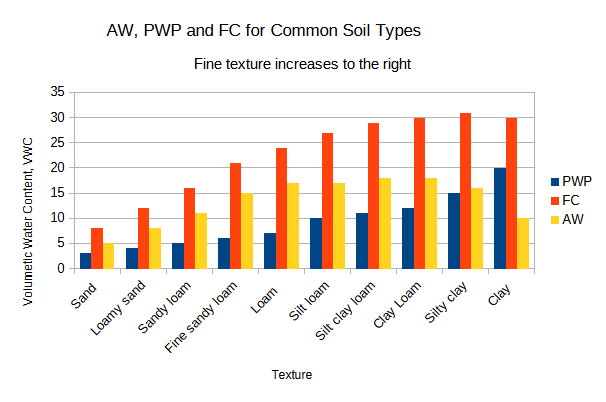
An area that has been flooded will have gravity-driven drainage which will remove water from the larger pores. The water will continue to sink below the plants' roots and will then not be available. The threshold at which this happens is the Field Capacity, FC. For sand and clay the value of FC may well be 5 % and 30% by volume respectively.
Permanent Wilting Point (PWP)
Plants have a certain requirement for water and will extract this at a particular rate. There is a point at which plants cannot extract the required water because the soil binds it too tightly. At this point, the PWP has been reached. The PWP for sand and clay may well be in the order of 2 % and 20 % by volume respectively.
The plant's available water, AW, is given by:
AW = FC - PWP
So, for sand and clay we have:
Sand
% AW = 5% - 2 % = 3 %
Clay
% AW= 30 % - 20 % = 10 %
The overall observations are summarised in the following chart.
Soil Matrix Potential (SMP)
The SMP is a measure of the soil water tension, and plants must exert a force greater than this to extract water from the soil. As water declines in the soil, the SMP increases - so there is a relationship between % VWC and SMP. The units used to express SMP are kPa or centibar cb. The values are negative (due to it being suction).
The relationship between SMP and VWC is commonly referred to as a soil water retention curve and is soil dependent. It is not recommended to use "generalised" curves for this type of interconversion. The water retention curve is represented by the Van Genuchten model, such that:
θ(ψ) = θr + (θs - θr) / [1+(α |ψ|)n]1-1/n
Where:
θ(ψ) represents the water retention curve y ordinate (cm3 cm-3)
n is the measured pore size distribution, n >1
θs the saturated water content (cm3 cm-3)
θr the residual water content (cm3 cm-3)
α is allied to the inverse of the air entry suction (cm-1)
|ψ| is the suction pressure (cm).