
Operational Overview
The diagram below shows the specific parts of the sensor. Read on to learn more about the function of each component.
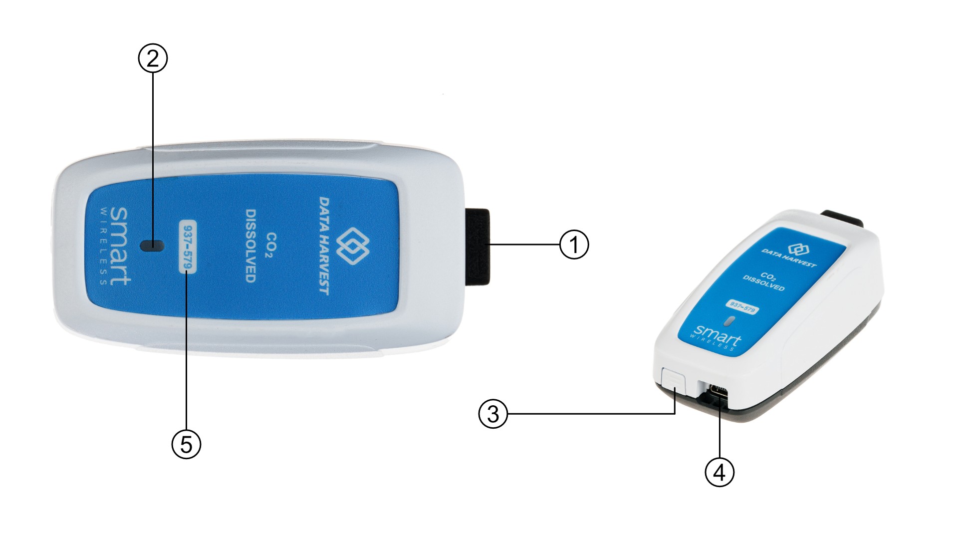
The End Cap (1)
The end cap provides a simple yet highly robust interface between the sensor and the electrode.
The Status Indicators (2)
The sensor features a single status indicator that changes colour and flashes. See the table below for further information.
|
Status Light |
Indicates |
|
|
No light |
|
Off |
|
Blue flashing |
|
On and Bluetooth advertising |
|
White flashing |
|
Charging via USB mains charger or USB port, On and Bluetooth advertising |
|
Red, Green, Blue Flashing |
|
Charging via USB mains charger or USB port, sensor is Off |
|
Green flashing |
|
Communication with the EasySense app (via USB or Bluetooth) has been established |
|
Solid Green |
|
Fully charged |
|
Orange flashing |
|
Recording data, a fast pulse indicates awaiting trigger in Remote Mode |
|
Red flashing |
|
Battery is low |










The Power Button (3)
A simple On/Off button. This requires a single hold to activate and deactivate the device.
The USB Connector (4)
This provides both power an connectivity (no USB mode)
Serial Number (4)
A unique identifier that allows users to connect to the device. This is especially useful in a multi-instrument environment.
The Sensor and EasySense
Ensure that the latest release of the EasySense software is installed. EasySense provides full support for data acquisition, storage, and analysis across multiple operating systems.
Direct Data Logging
The sensor is designed for direct operation with EasySense, either as a locally installed application or as a Progressive Web App (PWA). When connected via Bluetooth™ or USB, the sensor supports real-time data acquisition, live visualisation, and immediate data storage within EasySense. All supported experimental protocols can be executed in this configuration.
Remote Data Logging
Autonomous data acquisition is supported through EasySense Remote Mode, allowing the sensor to operate independently of a host device.
Remote Mode is accessed via Setup within EasySense. After configuring the sampling parameters and trigger conditions, data acquisition can be initiated locally on the sensor (for example, via a rapid press of the power button). Once acquisition has been initiated by the software, the sensor may be disconnected from the host device and will continue to collect and internally store data according to the predefined parameters.
Recorded data is retrieved by reconnecting the sensor and accessing Setup within EasySense.
Comprehensive configuration, operational limits, and data management procedures are detailed in the latest EasySense User Guide.