Usage Information
Setting the range
To alter the range in the EasySense software:
- Select Devices
- Select the Drop-down arrow on the sensor name
- Select the range required from the selection available
- Close the Devices box
- Select Finish to exit the wizard
Using the Drop / Bubble Counter to count drops
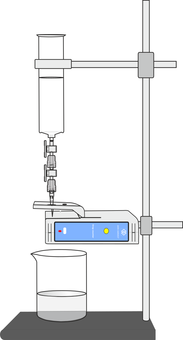
Setting up the reagent reservoir and alignment adapter
The plastic reagent reservoir and tip supplied with the counter will provide drops within the preset calibration ranges. The reservoir has two stopcocks. One stopcock is used to set the rate of flow from the reservoir and therefore the drop rate. The other stopcock is used to turn the drops on and off.
Assemble the plastic reagent reservoir
Screw a stopcock fitting onto the syringe body with a gentle half turn. Fit the second stopcock onto the first, then the tip. Turn both threaded collars to secure the fittings in place (twist back to release).
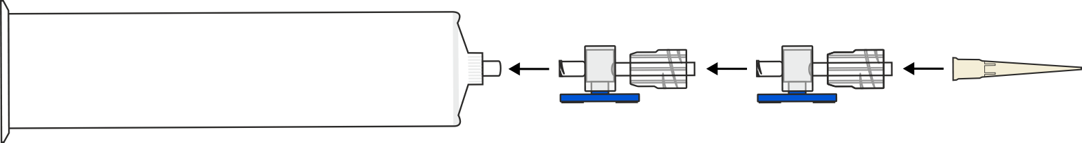
The combination of two three-way stopcocks is used to control the flow of fluid from the reservoir. The top stopcock is used as an adjustment valve to set the rate of flow and therefore the drop rate from the reservoir. The lower stopcock is used in either an open or closed position to turn the drops on and off.
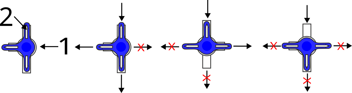
The stopcock has three ports and a three-point valve. The part of the stopcock labelled (1) has no port; if any point of the valve is directed to this position, flow is not possible in the flow indicator (2) direction. Flow is shown by the flow indicator marker (2). The part of the blue valve that has no handle or flow indicator has no opening. By moving the valve, you can direct the flow. Some examples are shown in the diagram.
Note: Leave the white sealing blank fitted to the side port of the stopcock.
Turn both stopcocks into the closed position. Clamp the reagent reservoir into place using the alignment adapter.
Using the alignment adapter
The alignment adapter has been provided to give an easy way of aligning drops through the infrared beam of the counter. The adapter has three holes in its flat plate.
Note: the adapter supplied with the wired Wireless Drop Counter will not align correctly if used with this apparatus.
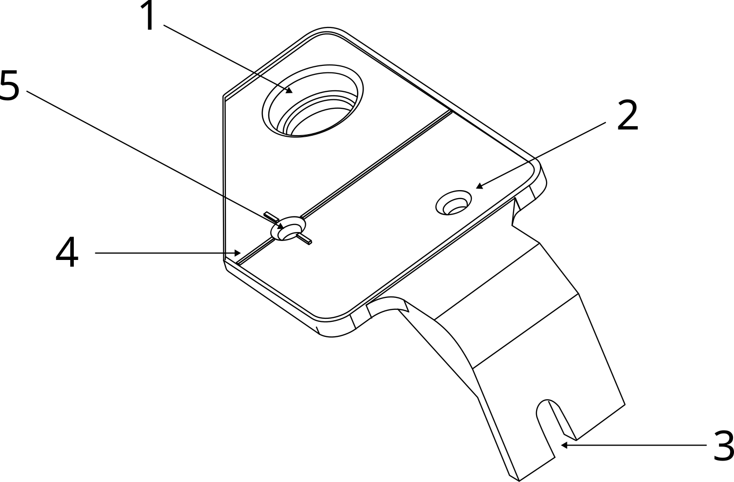
- Large hole for an electrode (e.g. pH, conductivity).
- Small hole for a temperature probe.
- Slot for mounting to body of drop counter.
- Alignment guide describes the light pat from transmitter to receiver.
- Location for the reservoir drop point. Positions the drops to fall through the light path.
Attach the alignment adapter to the Counter:
- Part screw the Pozi-drive pan-head screw supplied into the mounting thread between the two ridges in the centre of the Counter.
- Slide the mounting arm of the adapter behind the screw head.
- Gently tighten the screw, do not over tighten.
Calculating which Volume range to use
The Drop / Bubble Counter can be used record data directly as a volume (in cm3) measurement by selecting one of the preset calibrated ranges: 23 drops cm-3 ; 24 drops cm-3 ; 25 drops cm-3 ; 26 drops cm-3 ; 27 drops cm-3 ; 28 drops cm-3 and 29 drops cm-3.
If accuracy is not critical, and you are using the reagent reservoir and tip supplied with a low viscosity liquid (like water), and the flow rate is set to:
- Fast e.g. 10 plus drops per second, use the 24 drops cm-3 range.
- Medium e.g. between 5 – 10 drops per second, use the 25 drops cm-3 range.
- Slow e.g. between 1.5 – 5 drops per second, use the 26 drops cm-3 range.
- Very Slow e.g. less than 1.5 drops per second, use the 27 drops cm-3 range
Note: When used with a pH or Conductivity Sensor, the flow rate needs to be very slow (less than 1.5 drops per second) to allow the Sensor time to settle to a new reading after addition of the titrant.
To calculate the number of drops in a cm3
The volume of a drop of fluid (and therefore the number of drops per cm3) depends on a number of factors.
These include the:
- Size and shape of the dropper end
- Type of solution (its density, viscosity, and surface tension)
- Flow rate of the liquid through the dropper end (the slower the dropping the smaller the drop)
- Set up the reagent reservoir in the alignment adapter of the Counter. Close both stopcocks (a) and fill the reservoir with the solution being used.
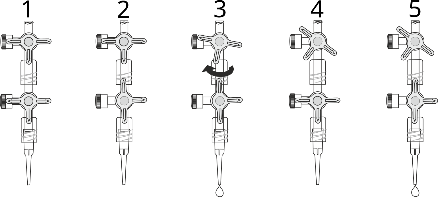
- The first step is to adjust the flow rate. Place a beaker under the stopcock to catch the drops. Fully close the lower stopcock and upper stopcock (1).
- Fully open the lower stopcock, leave the upper stopcock closed (2).
- Slowly turn the top stopcock until it begins to produce drops and then finely adjust the drop rate (3).
- When the correct flow rate of drops is achieved close the lower stopcock to stop the flow (4).
- Now the ‘flow rate’ is set, do not adjust the top stopcock – leave in this position. Use the lower stopcock to turn the drops on and off (5).
Note: Do not set the flow rate too fast or the drops may form a stream and will not be counted as individual drops. - Top up the reservoir. Place the accurate measuring container e.g. volumetric flask (10 cm3 or less) under the dropping tip.
- Set the range of the Counter to Drop/Bubble (Count). Press the zero reset button.
- Open the lower stopcock fully and count the number of drops required to fill up to the volume mark on the measuring container. Use the lower stopcock to turn the drops off.
Notes:
Make sure the lower stopcock is fully open or the rate of flow (and therefore the number of drops per cm3) will be affected.
Divide the number of drops by the volume (in cm3) to get the drops per cm3 value e.g. 272 drops fill a capacity of 10 cm3 = 27.2 drops cm-3. Top up the reservoir and repeat three times to get an average value.
Using the drop bubble counter for an accurate titration
The drop counter counts individual drops as they pass through the light path of the counter. The sensor uses infra-red to count the drops. The drops to be counted must absorb some infra-red to change the light path intensity. Water or aqueous solutions work well.
With a drop rate of 1 drop per second and the supplied tip used to form the drops, the default range of 27drops per cm3 should be used.
Use the stopcock closest to the reservoir as a rate valve and the lower stopcock as the on/off valve.
For even more precise counting, the drops per cm3 will need to be found using a small volumetric flask and use the drops range to find how many drops to fill the volume.
It is advisable to check that the drops are being counted before tightening the apparatus. The alignment shield will take much of the guesswork out of the set up, but if the reservoir is not true vertical, the drops formed can potentially miss the infra-red light beam.
A burette can replace the reservoir and stopcock setup. However, the single stopcock of the burette may make it more difficult to create an even flow of drops. A burette will probably need calibration as not every burette point is the same.
For simplicity, the example apparatus does not show the pH sensor in position. The alignment plate has a large hole to accept a pH electrode. If required, the light path of the sensor can travel through the glass of the beaker with the proviso that the glass does not absorb infra-red or is not so thick it blocks the light.
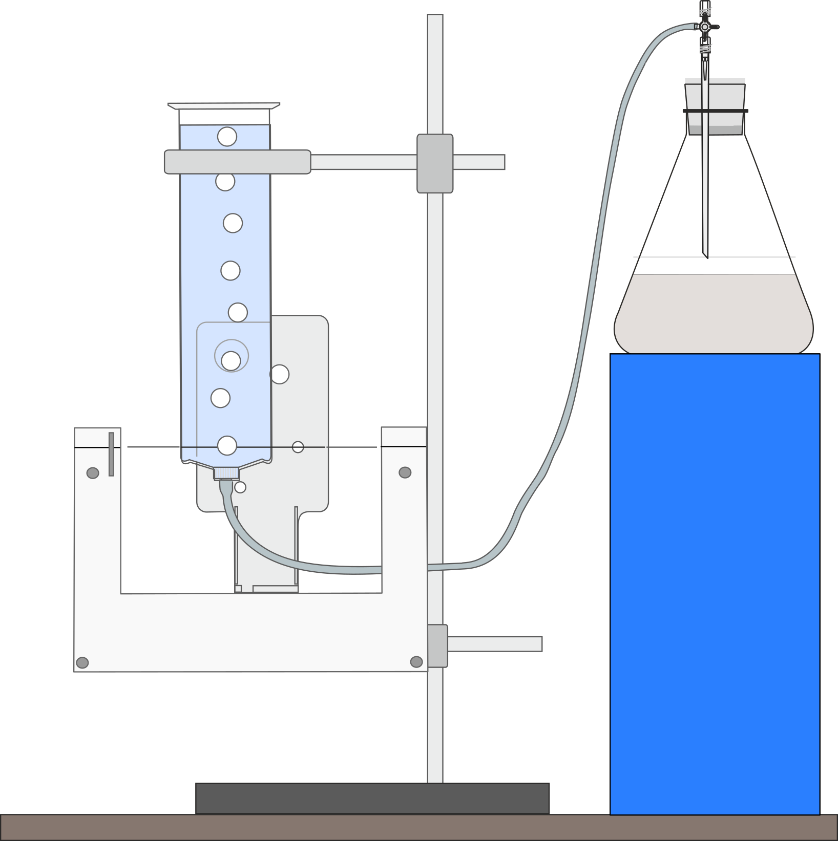
Using the Drop / Bubble Counter to count bubbles
The Drop / Bubble Counter can be used to detect a bubble formed in a column of water. The column of water should be positioned between the Counter’s receiver and emitter, so it blocks the infrared beam. When a bubble rises, the beam is momentarily changed, and a bubble is counted.
Bubbles cannot be calibrated for volume but can be used to show the change of gas production over time.
Test your set up before beginning the experiment. It is critical that the column of fluid is positioned so the bubbles will change the beams level as they rise. Bubble counting is not an exact science. Bubbles have an inconsistent format and can move through the fluid in an erratic manner; they need to rise separately from the same origin to be counted.
Note: Small, fine bubbles such as those produced by oxygenating pond weed are unlikely to be detected.
- Set the range of the counter to Drop/Bubble Count.
- Set up the column of fluid for the bubbles to rise through.
The reagent reservoir can be used as a vessel for counting bubbles. Connect a length of PVC tubing (3 mm inside diameter) from the reservoir to a stopcock attached to the delivery tube on the apparatus. Turn the stopcock to a closed position. - Clamp the Counter vertically.
- Clamp the reservoir and position in the gap between the receiver and emitter so that the reservoir is touching the emitter’s moulding.
Adjust the Counter or reservoir vertically so the moulding ring at the bottom of the reservoir barrel is level with the lower edge of the emitter moulding.
Adjust the reservoir laterally so the reservoir is just touching the moulding of the large hole in the alignment plate. In this position bubbles rising should pass through the light path between the receiver and emitter.
Note: You may need to make fine lateral adjustments of the reservoir.
Check the reservoir is vertical and parallel to the Counter.
Note: Try to keep the experimental apparatus higher than the water level in the reagent reservoir to prevent backflow of water into the experimental apparatus.
- Pour approximately 10 cm3 of water into the reservoir.
- Test to make sure the bubbles cause the red LED indicator on the Counter to blink as they rise through the water.
- Press the zero reset button on the Counter. Run the experiment (remember to turn the stopcock to an open position).
Practical information
- The fastest speed that data can be captured is 50 Hz (20 ms). If an inter-sample time of less than 20 ms is selected, then the values obtained will either default to the lowest reading or the set up will be rejected by the logger/software.
- A replacement parts pack for the Counter reservoir is available from Data Harvest, which contains 2 x 3-way stopcocks and 5 plastic tips - use Product No. 3271.
- The Drop / Bubble Counter works by recording interruptions of a beam of infrared energy. The receiver can be sensitive to high levels of ambient infrared light or heat. Shield the Counter from bright light e.g. sunlight, which can produce a false OFF result. Work in an area away from direct light or rotate through 180˚ so the external light source is directed towards the emitter.
- Any calculations for drops per cm3 will only be valid for the same dropper with the same type of solution and flow rate.
- If the flow rate is too fast the drops will merge to form a continuous stream. The flow rate should be set so that each drop passes through the Counter before the succeeding drop.
- With a titration use a very slow drop rate (e.g. with a maximum speed of 1.5 drops a second) so the drops can add to and mix thoroughly with the reactant, allowing the electrode time to respond.
- If you use a burette as a reservoir you will need to devise a method of stopping the flow from the burette without altering the drop rate. If the burette has a replaceable tip, use a length of plastic tubing to link the tip to the burette. A tube clamp can be used to crimp the plastic tubing and shut off the flow. A bung inserted into the top of a burette will also prevent flow and can be used as a ‘flow stop’. During test we found a standard 50 ml burette produced 23 or 24 drops per cm3 (depending on flow rate).
- Volume measurements are calculated by using the ‘drops per cm3’ data so there is no need for the reagent reservoir to have a volume scale.
SI units: Volume is a measurement of the space occupied by a body. The SI unit of volume is the cubic metre (m3). The volume of a liquid is calculated from the space it takes up in its containing vessel. The internal volume of the containing vessel is called its capacity. The SI unit of capacity is the litre (L) - equal to 10-3 m-3 (1 ml = 1 cm3).