Operational Overview
The diagram below shows the specific parts of the Wireless Switch Sensor.
Read further to explore the functionality of each part.

- Sensor End Connector
- Status Indicator
- On/Off Switch
- USB Port
- Unique ID Number
- Switch State Indicator
Sensor End Connector (1)
Most Smart Wireless Sensors feature an end cap that is specific to the requirements of the device's internal sensor. The sensor's end cap is the direct interface between the device’s internal sensor and your experiment.
Status Indicators (2)
The sensor features a single status indicator that changes colour and flashes. See the table below for further information.
|
Status Light |
Indicates |
|
|
No light |
|
Sensor is Off. Short press the On/Off switch |
|
Blue flashing |
|
Sensor is On and Bluetooth advertising |
|
White flashing |
|
Charging via USB mains charger or USB port, Sensor is On and Bluetooth advertising |
|
Red, Green, Blue Flashing |
|
Charging via USB mains charger or USB port, Sensor is Off |
|
Green flashing |
|
Communication with the EasySense app (via USB or Bluetooth) has been established |
|
Solid Green |
|
Fully charged |
|
Orange flashing |
|
Recording data, a fast pulse indicates awaiting trigger in Remote Mode |
|
Red flashing |
|
Battery is low |
On/Off Switch (3)
The sensor's on/off switch allows you to turn the sensor on, off or perform a hard reset.
To switch the sensor off
- Press and hold down the On/Off switch until the white light shows, then release.
- If not communicating with the EasySense app, the sensor will turn off after a period of one hour of inactivity.
Hard resetting of the sensor
- If necessary, attach the sensor to power.
- Press and hold down the On/Off button for at least 8 seconds until the status LED gives a flash of blue light, then release.
- If the sensor fails to respond, contact Product Support at Data Harvest. Please provide details of:
- The computer platform it is being used with and the EasySense app’s version number.
- A description of the problem being encountered.
USB Port (4)
Use to connect to a computer or a charging unit.
For specific USB or Bluetooth connectivity instructions, please see the 'Connectivity' section of this documentation.
For instructions on charging your device, see the section on 'Charging the Sensor'.
Unique ID Number (5)
All Smart Wireless Sensors are labelled with a unique ID number. This number is used in the EasySense app, so that you can identify each sensor when making a connection wirelessly.
Switch State Indicator (6)
This provided confirmation that a switch has been pressed.
The Timing Mat
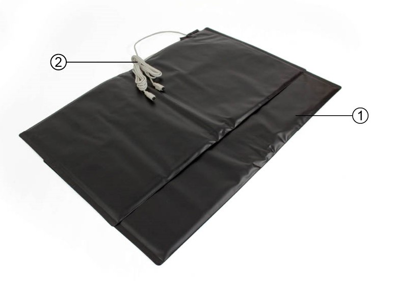
Timing Mat Sensor (1)
This rugged surface provides the pressure sensitive surface for measuring events.
Connector Lead (2)
Two connectors are shown, one is attached to each of the mats. A " mini-DIN" provides a link from here to the Wireless Switch Sensor (above).
Mini-DIN to 3.5mm Jack Connecting Cable

Connection for the Switch Sensor (mini-DIN) (1)
Connect this end to the switch sensor's jack input.
Connection for the Timing Mat (2)
Connect this end to the timing mat connecting lead (above).
The Sensor and EasySense
Please make sure that you use the latest release of the EasySense series of software. Both collection and analysis of data is available here, on a variety of operating systems.
Direct Data Logging
The sensor is designed to work directly with EasySense (as an installed application or PWA). A full compliment of experiments can be run by using the sensor through BluetoothTM or USB. EasySense will support direct logging and data storage when connected as above.
Remote Data Logging
The ability to capture data independently (free of a capture station) is done through EasySense’s Remote Mode.
This facility may be found in EasySense, under Setup. Once the conditions for data collection have been established, the sensor can be set to initiate collection for example, using a rapid press of the power button. Initiation of the experimental data collection by the software is followed by remote detachment; collection is then on the sensor.
Data gathering is realised by using Setup once again.
Details are given in the latest EasySense User Guide.