Operational Overview
The diagram below shows the specific parts of the sensor. Read further to explore the functionality of each part of the sensor.
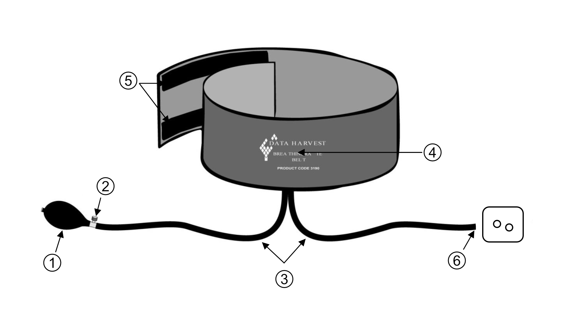
- Hand pump bulb
- Release valve
- Rubber tubes
- Air bladder (fitted inside the belt)
- VelcroTM strips
- Attachment tube
Hand pump bulb (1)
PLEASE AD A DESCRIPTION HERE
Release valve (2)
PLEASE AD A DESCRIPTION HERE
Rubber tubes (3)
PLEASE AD A DESCRIPTION HERE
Air bladder (4)
PLEASE AD A DESCRIPTION HERE
Velcro Strips (5)
Adjust to secure the breathing rate belt around the persons chest.
Attachment tube (5)
Attach this part of the rubber tube to P1 on the Differential Gas Pressure Sensors.