
4.2.3.2 Timing Locations
The following descriptions show how the location(s) define the measurements.
Measurement at A
Uses one digital sensor connected to Input A. Timing starts when the signal from Input A changes (ON) and stops when the signal reverts (OFF).
If Light Gates are used with a single interrupt card, the time measured is for how long the card took to pass through the sensor.
For a Push Switch it will be the length of time that the switch is kept depressed.
For Timing mats, it will be the length of time someone stands on the mat or jumps between the two mats.
Measurement at A or B
Uses two sensors connected to Input A and B. A measurement will be taken from whichever sensor detects the change in signal level. The measurement will be the time to pass through either sensor A or sensor B.
Measurement from A to B
Uses two sensors connected to Input A and B. A measurement is taken for the time an object takes to travel from the sensor at Input A to the sensor at Input B. Timing will start when the signal change at Input A is detected and stops when the signal at Input B changes.
Measurement at A then B
Uses two sensors connected to Input A and B. Three measurements are recorded of an object travelling from the sensor at Input A to the sensor at Input B. The measurements are:
1.Time to pass through Sensor A
2.Time to pass through Sensor B
3.Time to travel from A to B
Measurement at A then A
Uses one digital sensor connected to Input A. Time will be measured for a single interrupt card passing through a Light Gate (A1), and then returning through (A2). E.g. for rebound collisions.
Measurement from A to A
E.g. stopwatch. Uses one digital sensor connected to Input A. Timing will start when the signal at input A changes (ON) and will continue until the signal at A goes OFF and then ON again.
Change From A to A
Uses one digital sensor connected to Input A. The measurement will be for the change in value from A2 to A1 e.g. for a single interrupt card passing through a Light Gate and returning through.
Change From A to B
Uses two sensors connected to Input A and B. A double interrupt card is used to measure the acceleration at A and then at B. The measurement shown will be the change in acceleration (Acceleration at B – Acceleration at A).
Distance at A
Use the Picket fence or Pulley, with a Light Gate connected to Input A, to measure the distance moved. Distance is calculated using the step size of the Data Harvest Pulley, or the pitch length of the Picket fence. Each time a new gap in the Pulley or the pitch of the Picket fence is reached; the distance moved is known.
Period at A
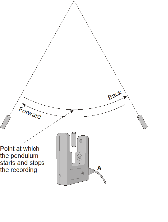
E.g. pendulum
State A and B
Timing is usually started when the solid black part of an interrupt card blocks the infrared beam on a Light Gate and changes the logic level from 0 to 1. When the clear part of the card is reached, the infrared beam is restored, and its logic state changes back to zero and the event time is taken. Raw times show the logic as 0 and 1 with the time of the event.